Xinfa welding equipment has the characteristics of high quality and low price. For details, please visit: Welding & Cutting Manufacturers – China Welding & Cutting Factory & Suppliers (xinfatools.com)
Welding method: manual arc weldingJoint type: plate butt jointWelding position: overhead weldingTest piece material: Q345R (16MnR)Test piece specification: 300×100×12mmWelding rod model: E5015Welding rod specification (mm): Φ3.2 Φ2.5Current type and polarity: DC positive connection method (base welding) DC reverse connection method (filling, cover welding)
01 Groove form
V-shaped groove 60°±5° Blunt edge: 0 mm
02 Preparation before welding
Grind the groove of the test piece to ensure that there is no water, oil, rust or other impurities at 20mm on both sides of the groove, and expose the metallic luster. The welding rod needs to be dried before use, heated to 350℃, and kept warm for 2 hours.
03 Group diagram
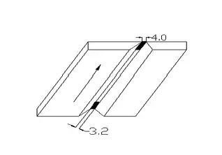
Reserved anti-deformation: 3°-4° Assembly gap: 3.2-4.0mm Misalignment: ≤1 mm Spot fixation position: both ends of the test plate weld Spot fixation welding length: 10mm
04
Main welding parameters
05 Operation points
⑴ Base welding: ① Arc striking position When base welding, strike the arc at the small gap of the test plate to locate the weld, pause for preheating, pull the electrode to the gap of the groove, push the arc upward, melt the root of the groove and break through to form a molten hole. ② Rod moving method and electrode angle Use a small sawtooth rod moving, lateral swing, short arc, and continuous forward welding. The electrode angle is shown in Figure 1.
③ Control the molten hole and molten pool. The arc stays for a while on both sides of the groove root. The pause time is shorter than that of other plate specimens. The groove root should melt 0.5-1mm on both sides, and the molten pool should be small and shallow. ④ Weld joint. When the arc is closed, the electrode is pulled back 10-15mm to the left or right groove surface in the opposite direction of welding, so that the joint is inclined. Weld joints are made by hot or cold connection. When the arc is ignited on the groove surface about 10mm in front of the arc pit and the arc is moved to the front edge of the arc pit, it is pushed to the back of the weld root and paused for a while. After the molten hole is formed, the arc is restored to the normal welding length and welding is continued. When the cold connection method is used, the arc pit is polished into a gentle slope before welding.
⑵ Filling welding:
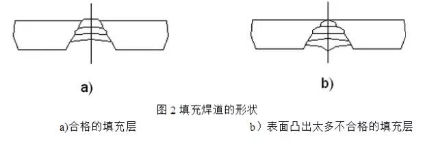
① Before filling welding, remove the slag and spatter of the previous weld. ② The electrode angle and the method of moving the electrode are the same as those of the base welding, with a larger swing amplitude and a horizontal swing to the corner for a while. When welding the second layer of filler weld, the wire feeding speed in the middle of the weld should be slightly faster, so that the middle of the weld is slightly concave, as shown in Figure 2. The thickness of the filler layer weld should be about 1mm lower than the surface of the parent material. ③ When filling the weld joint, strike the arc 10mm in front of the arc pit, return the arc to the arc pit, fill the arc pit along the shape of the arc pit, and then weld normally.
⑶ Cover welding: When welding the cover layer, the electrode angle, electrode feeding method, and joint method are the same as the filling layer. The arc should be lowered and paused on both sides of the groove, and it should be slightly faster when swinging from one side to the other to avoid undercutting and weld nodules.
06 Welding requirements
① There should be at least one arc stop and re-weld joint near the middle of the length of the first layer of weld; ② Welding must be done from one side; ③ Except for the joint part of the first and middle layer welds, grinding and repairing are not allowed for other welds when changing the electrode; ④ It is not allowed to use welding fixtures or other methods to rigidly fix the plate specimen, but it is allowed to reserve the reverse deformation amount when positioning the specimen; ⑤ The specimen is required to be fully welded; ⑥ The number of specimens requires 1 weld, and multiple welds are not allowed to be selected.
07 Appearance inspection
Inspection method: ①Use macroscopic (visual or 5x magnifying glass, etc.) method; ②Defects within 20mm at both ends of the test piece are not counted; ③The height and width of the weld can be measured by the weld inspection ruler. The maximum and minimum values are not averaged; ④The width of the back weld can be omitted.
Basic inspection requirements: The weld surface should be in the original state after welding, and the weld surface should not be processed, ground or reworked. Inspection content and evaluation indicators: ① There shall be no cracks, lack of fusion, slag inclusions, pores, weld nodules and incomplete penetration on the weld surface; ② The undercut depth is less than or equal to 0.5mm, and the total length of the undercut on both sides of the weld shall not exceed 30mm; ③ The depth of the back pit is not more than 2mm; ④ The weld excess height is 0-4mm; ⑤ The weld excess height difference is ≤3mm; ⑥ The weld width: 0.5-2.5mm wider than each side of the groove, and the width difference is ≤3mm; ⑦ The weld excess height on the back is not more than 3mm; ⑧ The weld straightness f≤2mm; ⑨ The deformation angle of the test piece after welding is less than or equal to 3°;
Post time: Jan-06-2025


